System Troubleshooting
Firmware
In order to troubleshoot the FPGAs on the support board and detector board, one can use a JTAG connection. For the support board, to test just the Main FPGA, use the JTAG along with the green jumper board as it is set up for normal operations (Fig. 66).
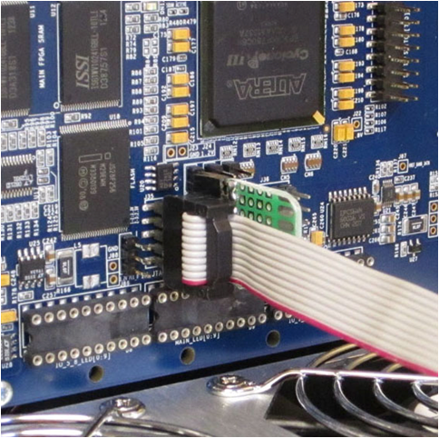
Fig. 66 Image of the JTAG connected to the support board.
To test the Main and IO FPGAs simultaneously, remove the green jumper board and use the JTAG chain depicted in Fig. 68. Each circle in the image represents a pin. The picture is rotated 90 degrees clockwise compared to how the pins are actually oriented on the board in the crate as can be seen when comparing Fig. 67 to Fig. 68. Jumpers and shunts are used to connect the pins.
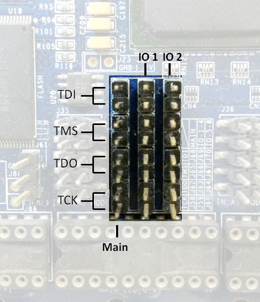
Fig. 67 Picture of the pins used in the JTAG chain
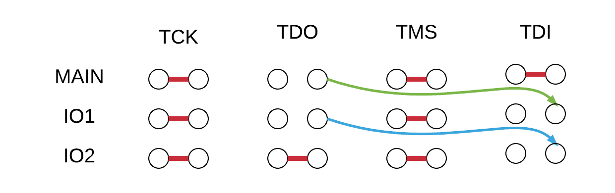
Fig. 68 Diagram of the JTAG chain for debugging Main and IO FPGAs on the support board.
For the detector board, only the JTAG need be connected. This is shown in Fig. 69.
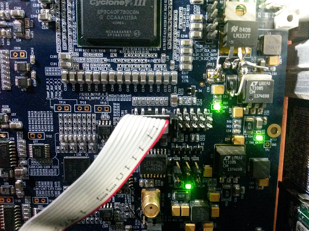
Fig. 69 Image of the JTAG connected to the detector board.
Embedded Software
With the JTAG connected, one can see what happens in NIOS for the support board and detector board. After connecting the JTAG to the desired board, open the NIOS command shell and then run the nios2-terminal executable. Now, when a command is sent to the system, the progress in NIOS can be seen. Fig. 70 shows an example of this output.
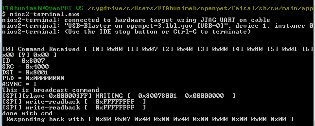
Fig. 70 Image of the NIOS command shell when a command is sent to the system.
Additionally, one can see what happens during the bootup sequence of the support board as shown in Fig. 71.
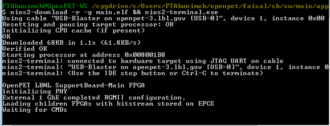
Fig. 71 Image of the NIOS command shell during the bootup sequence.
If one wants to see NIOS on both the support board and detector board simultaneously, connect a JTAG to each board and open two NIOS command shells. In one window, run the nios2-terminal command specifying which JTAG cable is to be used by adding a parameter. In the command nios2-terminal -c1, the parameter c1 indicates the cable in slot 1 is to be used. To set up the second window, run nios2-terminal -c2 to view the information from the second board.
To determine what cables are connected to the system, there is a command jtagconfig that shows the list of cables. However, to determine which cable is connected to which board, one must physically look at the system setup.
For more NIOSII command-line tools, see this page